- Document History
- Subscribe to RSS Feed
- Mark as New
- Mark as Read
- Bookmark
- Subscribe
- Printer Friendly Page
- Report to a Moderator
- Subscribe to RSS Feed
- Mark as New
- Mark as Read
- Bookmark
- Subscribe
- Printer Friendly Page
- Report to a Moderator
Nintendo Communication in the "eyeMario" Video
This document originally appeared in 2010 with an accompanying video. It has been moved to the NI Community where it can be more easily found and enjoyed.
1. Overview
In the Waterloo Labs episode eyeMario, the team used digital lines from an NI Singleboard RIO to communicate with a Nintendo Entertainment System. Custom circuitry was built on an NI Singleboard RIO daughter card that simulated a standard controller, allowing them to play classic video games using only eye moement. This document will provide an overview of the techniques used to accomplish this.
2. How NES Communication Works
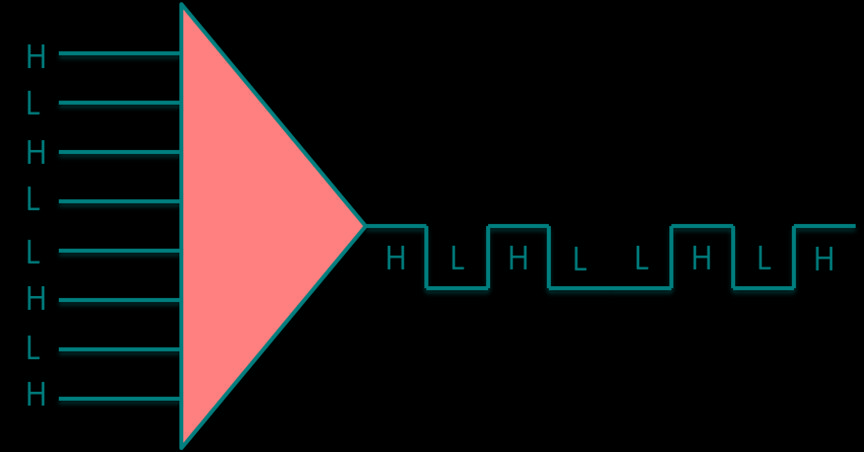
A standard Nintendo controller for an NES utilizes a 4021 shift register to turn 8 parallel digital lines into a serial data (Figure 1).
 Figure 1. A shift register serializes digital lines.
Each of the 8 digital lines is a button, such as Up, Down, A, or B. These lines are tied high to 5V through a pull-up resistor. When the button is pressed on the controller, these lines are shorted to ground, causing the digital line to go from high to low.
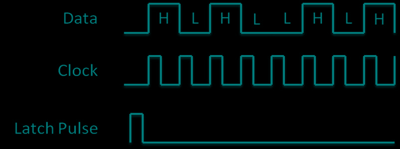
The shift register requires both a latch signal and a clock from the Nintendo to serialize the digital lines. When it receives a latch signal it locks the digital lines at their current values until they have been serialized and output. So if you press a button, such as Start, then the latch signal comes in and you then release Start before the signal is output, a low will still be serialized from the Start line because it was locked in. The clock is simply how fast the serialized data is output from the shift register.

Figure 2. The timing diagram of a shift register.
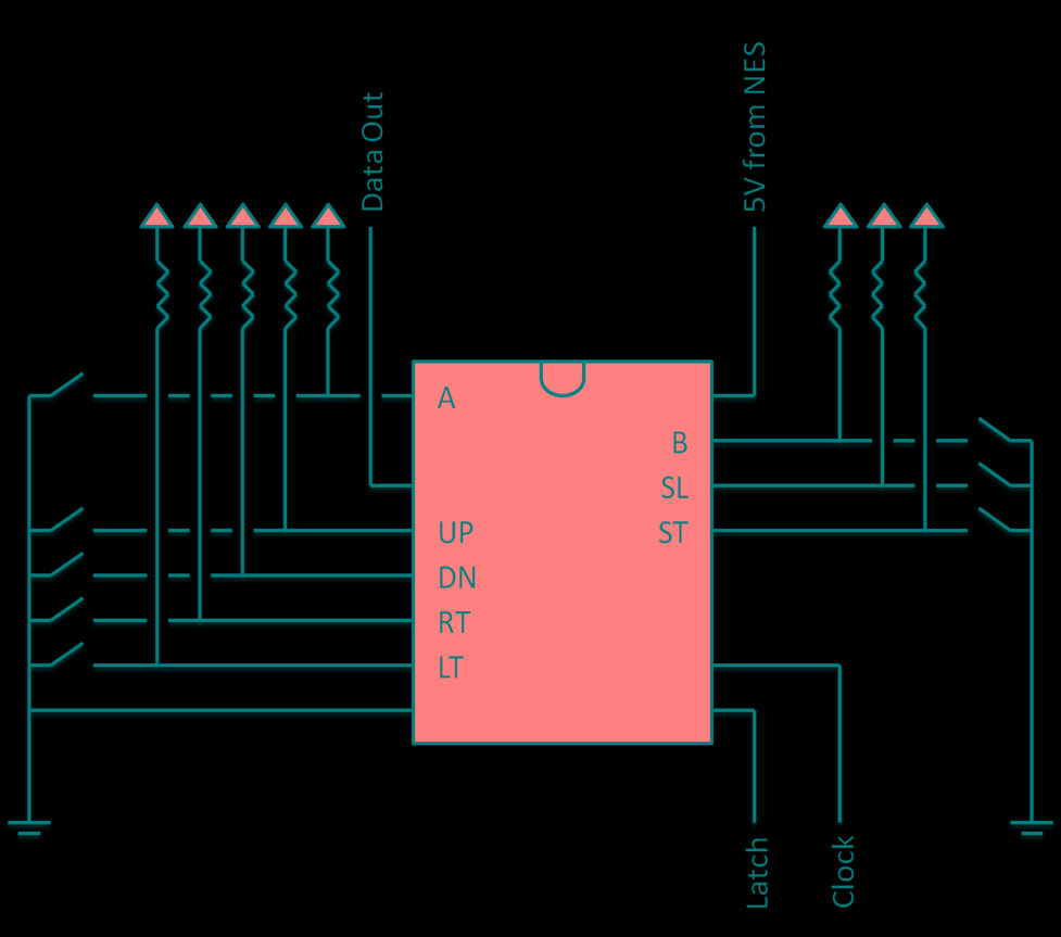
Wiring this all up to the shift register gives the schematic shown in Figure 3. The digital lines into the shift register are tied high to 5 volts through a resistor until the button is pressed, at which point the lines are grounded to 0 volts.

Figure 3. NES Controller schematic
The Data out, 5V from NES, Latch, and Clock are all supplied through the cable to the NES controller connector on the front of the Nintendo.
3. Implementation with NI Singleboard RIO
By replacing the digital lines and buttons with 8 digital lines from the NI Singleboard RIO it is possible to simulate the NES controller. Outputting a high 5 volt signal on all lines is the same as the controllers default of tying all lines high through a pullup resistor. To simulate a button being pressed, its corresponding digital line is simply output to 0 volts which is the same as grounding out the line in the controller.
4. Summary
By using the digital lines on a National Instruments Singleboard RIO and a 4021 shift register the Waterloo Labs team was able to successfully simulate the controller of an NES to play classic video games using eye movement.
