- Subscribe to RSS Feed
- Mark Topic as New
- Mark Topic as Read
- Float this Topic for Current User
- Bookmark
- Subscribe
- Mute
- Printer Friendly Page
Problems with "Print LCD" and "Analog Read"
04-24-2012 10:20 AM
- Mark as New
- Bookmark
- Subscribe
- Mute
- Subscribe to RSS Feed
- Permalink
- Report to a Moderator
Hi all, it's my first post !! I'm new to LabVIEW and Arduino.
I'm in this situation:
I recieve a voltage between 0 and 5 V in an analog input of the Arduino and I want to read this value and print it in a LCD display. It's only a small part of my project. The problem is that when I put the SubVI's "Analog Read" and "Print LCD" ( both from the Arduino's Toolkit) in the Block Diagram the Analog Read doesn't read properly (it reads impossible values as 60 Volts). However, after some invastigation, I have discovered that without the block "Print LCD" the Analog Read works perfectly ! I don't understand what's happening because in my Block Diagram there are a lot of SubVI's from Arduino's Toolkit ("Clear LCD","Digital Write","Cursor"etc.) and the Analog Read works great, the only problem is when I put "LCD print". I have to say that when I put both icons in the diagram, "Print LCD" works good, the problem it's only in the Analog Read. It seems that the "Print LCD" changes something and then the Analog Read couldn't calculate the voltage properly. LabVIEW doesn't show me any error message.
I think that is a problem of communication. I have been investigating inside the SubVI's but I don't have enough knowledge to solve the problem.
I have to say that all the experiments I have done with LabVIEW + Arduino have worked perfectly without any problem.
I use USB to communicate with my Arduino UNO.
I would be grateful if someone could give me some advice.
Thank you in advance !!!
04-30-2012 01:00 PM
- Mark as New
- Bookmark
- Subscribe
- Mute
- Subscribe to RSS Feed
- Permalink
- Report to a Moderator
Hey Jorxs,
Are you using the single sample analog input or the continuous sample analog input? You cannot use the continuous sampling mode at the same time as using other Arduino commands.
Principal Software Engineer
NI
04-30-2012 03:29 PM
- Mark as New
- Bookmark
- Subscribe
- Mute
- Subscribe to RSS Feed
- Permalink
- Report to a Moderator
Thank you for your response Kevin. I am using the single sample analog input.
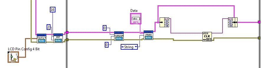
However, I've just solved the problem !!! After seeing that the current bytes at port were increasing with the "Print LCD" in the While Loop, I put a Visa Clear inside, and the problem has disappeared. It seemed a problem related to the flush buffer. Everything runs OK now. Thanks again !!
05-08-2012 10:36 AM
- Mark as New
- Bookmark
- Subscribe
- Mute
- Subscribe to RSS Feed
- Permalink
- Report to a Moderator
hey Jorxs,
I'm experiencing same problem, can you please be more specific about the solution. Maybe post a screenshot.
Thank you very much!
05-08-2012 11:44 AM
- Mark as New
- Bookmark
- Subscribe
- Mute
- Subscribe to RSS Feed
- Permalink
- Report to a Moderator
Hi Naaf, I solved the problem including a VISA Clear after the Print LCD block. I post a screenshot of this part to make it clear. It's a very specific problem and maybe there are other ways to fix it.
03-16-2014 08:27 AM
- Mark as New
- Bookmark
- Subscribe
- Mute
- Subscribe to RSS Feed
- Permalink
- Report to a Moderator
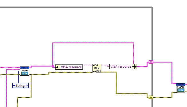
Hii Jorxs, where to you get the "VISA resource"? As I can't find it in my palette.. please help me, I have same problem as you too but not able to solve it.
03-16-2014 12:16 PM
- Mark as New
- Bookmark
- Subscribe
- Mute
- Subscribe to RSS Feed
- Permalink
- Report to a Moderator
"VISA resource" in his picture above is not a VI, it's an element of the Arduion Resource cluster that contains the VISA resource that the Arduino is using (e.g. "COM3"). This could be why you are getting strage values from your analog pin.
05-10-2014 01:43 PM
- Mark as New
- Bookmark
- Subscribe
- Mute
- Subscribe to RSS Feed
- Permalink
- Report to a Moderator
Still, how can I get it, I don't find it anywhere... could you post how to get the "VISA resource" before the CLR?
05-10-2014 01:49 PM
- Mark as New
- Bookmark
- Subscribe
- Mute
- Subscribe to RSS Feed
- Permalink
- Report to a Moderator
I fixed it using the bundle and unbundle functions.
03-15-2015 01:39 PM
- Mark as New
- Bookmark
- Subscribe
- Mute
- Subscribe to RSS Feed
- Permalink
- Report to a Moderator
Hello,
I have the same problem is you had. I tried with Visa celar, but it doesn't help. "Analog Read" and
"Digital Input Read" still doesn't work right.
I used Unbundle and Bundle before and after VISA CLR. Do you have any idea what else could be wrong?
I'm using Labview 12 and Arduino Mega 2560.
Please help ASAP,
Thank you a lot.