- Document History
- Subscribe to RSS Feed
- Mark as New
- Mark as Read
- Bookmark
- Subscribe
- Printer Friendly Page
- Report to a Moderator
- Subscribe to RSS Feed
- Mark as New
- Mark as Read
- Bookmark
- Subscribe
- Printer Friendly Page
- Report to a Moderator
Overview
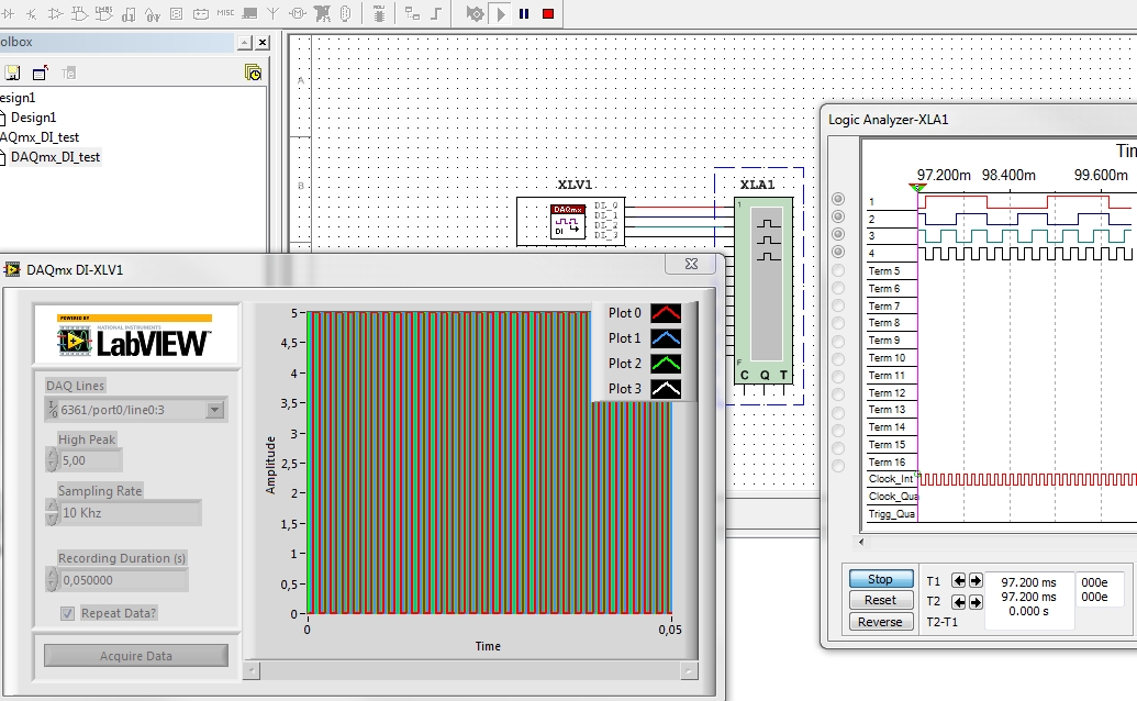
A very simple example to use a DAQmx Digital Input in MultiSIM. The internal frequency generator is
used to generate the sample frequency. for the digital inputs.
Steps to Implement or Execute Code
Unpack the archive to the Multisim installation directory. The table illustrates the files that will be copied to your harddrive.
Type | Name | Location | Application |
Instrument | DAQmx_DI.llb | ..\lvinstruments | Multisim |
Example | DAQmx_DI_test.ms13 | ..\ samples\LabVIEW Instruments\DAQ | Multisim |
Project | DAQmx_DI.lvproj | ..\ samples\LabVIEW Instruments\DAQ | LabVIEW |
Source | DAQmx_DI.llb | ..\ samples\LabVIEW Instruments\DAQ | LabVIEW |
Requirements
Software
LabVIEW 2013
MultiSIM 2013
DAQmx 9.7.5
Hardware
MultifunctionDAQCard, X-Series, M-Series
Instrument Features
The following describes the function of the various controls
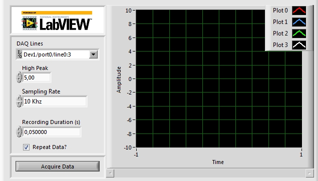
- DAQ Lines(s) specifies the names of the physical channels from a particular DAQ device. Select channels from the drop down list (press STRG to select multiple entries) or enter lines string manually (e.g. Dev1/ai0:3).
- High Peak specify the maximum value you expect to give out as an digital high.
- Sampling Rate specifies the sampling rate in samples per channel per second.
- Recording Duration (s) specifies the amount of time a DAQ operation will read input data
- #Data point = Recording Duration(s) * Sample Rate (Hz)
- Repeat Data? specifies if Multisim automatically repeats your acquired data. If you use periodic signals, it is recommended to only sample one period and check the Repeat Data? checkbox.
- Acquire Data will update the graph with a new set of input data.

How To Use This Instrument
If you are familiar with Dataacquisition from National Instrument, you will find it easy to use the DAQ Source instrument.
However, here are some simple steps we recommend to follow when using the DAQ Source for the first time.

Alexander
- Mark as Read
- Mark as New
- Bookmark
- Permalink
- Report to a Moderator
Hi,I want to know how a common user can add a custom LabVIEW Simulation, for example I want to use the NI DAQmx all function. In this case only show the digital function~
- Mark as Read
- Mark as New
- Bookmark
- Permalink
- Report to a Moderator
Hello fanyfaga
you can look at this examples
Outputting Signals from a Multisim Simulation to a NI DAQ Device
Input Signals From NI DAQ Device To Drive Your SPICE Based Circuit
How to Create a LabVIEW Based Virtual Instrument for NI Multisim
Hope it helps.
Alexander
