- Subscribe to RSS Feed
- Mark Topic as New
- Mark Topic as Read
- Float this Topic for Current User
- Bookmark
- Subscribe
- Mute
- Printer Friendly Page
Photon Counting, Time Stamping, and basic help with how DAQmx works
10-16-2006 05:38 PM
- Mark as New
- Bookmark
- Subscribe
- Mute
- Subscribe to RSS Feed
- Permalink
- Report to a Moderator
There is some seriously useful stuff in this thread and using the information within I frankensteined a VI that could count photons from two channels simultaneously. I'm running my clock at 80MHz and my "photons" (frequency generator) are coming in at 1Mhz, and as expected I am reading 80 cycles for every 1 "photon" cycle. However, the counter wants to sum every element, so instead of getting 80 every time I get 80 160, 240, 320...etc. etc. This is a problem because the 6602 card has a 32 bit counter so I expected I could only count up to (2^32)/80. Which is about 53.7 million. This is pretty much the case (it actually counts to 54044150 in the 1st counter and 53997480 in the 2nd, I don't quite understand why). If however, the counter would consistently return the single time period (ie. 80) every time I could merrily collect data for a lot longer (than it takes the computer to count to 54 million anyway).
I remember reading somewhere that calling the "start task" VI was supposed to tell the counter to sum counts and not using the VI would return "raw" counts, but with or without the VI I get the same summing result.
Any advice would be most appreciated.
Cheers,
CJ
10-17-2006 12:16 AM
- Mark as New
- Bookmark
- Subscribe
- Mute
- Subscribe to RSS Feed
- Permalink
- Report to a Moderator
2. To measure "delta time", you need to configure for period measurement. Attached is a screenshot showing what to do. Note the expanded menu showing how to access the property for defining the timebase.
3. If you're going to sample at a high rate, you're going to have to get the file writes out of your main data acq read loop.
4. The defaults on the vi you posted attempt to read more samples than the requested buffer size. I don't have real hw & signals for testing, but watch out for this.
-Kevin P.
10-17-2006 11:44 AM
- Mark as New
- Bookmark
- Subscribe
- Mute
- Subscribe to RSS Feed
- Permalink
- Report to a Moderator
Thanks for the reply, the default values aren't the values I use, I'm actually buffering 1,000,000 and reading 10,000.
I actually started with a period measurement method but gave up on that because it apparently did some sort of averaging to provide periods, which made me suspicious...
So I'll stick with counts for a while and see what happens...
I followed your advice and put the write file outside of acq loop (holy smokes that made it fast), but when I do that it only returns the last loop's values. So I tried changing the tunnels to shift registers but it still won't do it (I'm building the array within the acq loop). I'll rummage through some posts on the forums to figure it out, but if you have any advice on this point I'm grateful.
With the data writing within the acq loop and things running slower am I at risk of not getting true counts? That is to say am I actually missing counts when I do this? I just assumed that it took longer to update the screen, but because my buffer was large enough, all my counts were still being collected. If I can get away with it I might just leave the acq and writing in a single loop.
Cheers,
CJ
10-17-2006 01:07 PM
- Mark as New
- Bookmark
- Subscribe
- Mute
- Subscribe to RSS Feed
- Permalink
- Report to a Moderator
10-17-2006 01:13 PM
- Mark as New
- Bookmark
- Subscribe
- Mute
- Subscribe to RSS Feed
- Permalink
- Report to a Moderator
I also wanted the time between photon arrivals. If you have matlab available, I found it was very quick and easy to run the diff function on a list of arrival times to grab the time between arrivals. I used diff on lists of tens of millions of photon time stamps and it generally took less than a second. The reverse is also true. If you want to build up arrival times from the time between arrivals, the sum function runs just as fast.
10-17-2006 02:42 PM - edited 10-17-2006 02:42 PM
- Mark as New
- Bookmark
- Subscribe
- Mute
- Subscribe to RSS Feed
- Permalink
- Report to a Moderator
Not sure how the speed stacks up, but it's pretty easy to perform these functions within your LabVIEW program as well. Here's a screenshot:
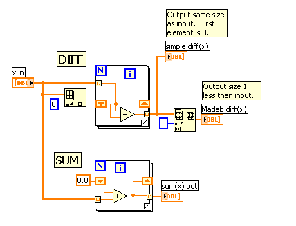
Under LV, the "natural" form of the diff function will produce an output with the same size as the input. A form that reduces the size by 1 (like Matlab) is likely to be a slower on average.
-Kevin P.
Message Edited by Kevin Price on 10-17-2006 03:43 PM
10-17-2006 02:48 PM
- Mark as New
- Bookmark
- Subscribe
- Mute
- Subscribe to RSS Feed
- Permalink
- Report to a Moderator
Kevin, I will give the period counting another go, I don't think I've ever tried using the single "Low Frequency" counter, since I cavalierly assumed 1+MHz meant High Frequency.
Thanks for the Producer Consumer link, I have plenty of info to review now.
Nepthar, thanks for the information, I'm glad to know Matlab processed it quickly, we've been using Matlab to run a correlation function and from what I understand it really bogs down when you get into the 90 million data points range...
Cheers,
CJ
11-10-2006 08:27 AM
- Mark as New
- Bookmark
- Subscribe
- Mute
- Subscribe to RSS Feed
- Permalink
- Report to a Moderator
I am trying to develop a quick algorithm to process the autocorrelation of photon arrival time. If any of you has some raw data of photon arrival time, I would really like to get them.
Thank you
@ChrisErven wrote:
Hi,
Thanks to anyone who can give me help. I've done some LabView programming with a DAC before in an older version of LabView, I'm just starting out with Counter/Timer applications with the new LabView and I'm trying to figure out what's going on. Information on exactly what's going on is hard to come by. I've spent the last two days going through most of the LabView help files and examples, and today I've been going through this forum. I'm hoping though that someone can provide me with an explanation as to what's going on.
My application: I'm trying to make an application that will provide highly accurate time stamps (using the 80MHz internal clock ~12.5ns) in a quantum key distribution experiment. What happens is I generate a photon pair, this pair then goes through an optical circuit and eventually each gets detected by a separate photon detector which outputs TTL pulses, these pulses are then meant to come into the counter and be stamped with a highly accurate event time, so two lists will be generated and a time correlation function will then be run on these lists to determine the paired events in each list.
My Hardware: PCI6602 counter/timer card, BNC-2121 board, LabView 7.1
My general idea of what I have to do: Have 2 counters running off of the 80MHz timebase to keep an accurate time, have an overflow counter so that when the counters reach their maximum they reset to zero and the overflow counter gets incremented (so that the experiment can run for longer then the size of the counters), have the 2 photon detector signals come in as the gates for the two counter channels, write a time stamp to a file every time the gates fire.
(I've included the code I have so far)
Steps I have so far:
1) Create a channel
- I've tried various things now to put a gate or a trigger in, Start Trigger complains about not having the right component, arm trigger seems to work but from what I've gathered from reading other posts I want a DAQmx Timing.vi to use as the Gate (using a Timing vi as the gate was not at all obvious to me), so how do I use the timing VI as a gate? Can you explain to me what each pin is doing and what's going on? I can look at example code easily enough myself, but I want to have an idea of what the heck is happening.
2) Start a task
3) Read the counter
- Alright so if I get the gate working, someone also told me that I have to use a buffered read so that the hardward continues to read the clock and there's no software latency issues, I'm going through the example Counter Digital Events-Buffered Continuous.vi again, but if someone can help me on what to do, and more importanly how things are working and why I'm doing things that would be great
- I also need a write function here to write time stamps to a file, anything I need to be aware of so that the write doesn't slow down the time stamping or anything else?
4) Stop Task
5) Clear Task
I need to keep all this going in some sort of loop as well until the end of the experiment, thoughts?
What does the DAQmx trigger.vi do? Because that's what I've been trying for the longest time to use and it hasn't been working.
As you can see I have two loops there, I was trying to make the vi continuous so that it could receive multiple events from the photon detectors, but what I've done is probably very ugly, is there a better way to set this up?
Lastly, if there are any good resources which EXPLAIN what components are doing and how to use them (I've gone through the help files on all the DAQmx components and they don't have much in depth info), I'm more then willing to do some work and learn how to do things myself, all I need are some good resources.
Thanks to anyone that can help me with this gigantic post, I really appreciate it 🙂
Chris
04-05-2007 03:29 PM
- Mark as New
- Bookmark
- Subscribe
- Mute
- Subscribe to RSS Feed
- Permalink
- Report to a Moderator
Hello everyone
I'm doing something similar to CJKS and have also been trying to work through this thread to understand DAQmx (with which I have almost no experience). Does anyone know what the best way would be to gate the measurement? Here's a brief explanation of what I am doing, and what I mean by gate:
I'm running two photon detectors into a 6602 board. I want to count the digital pulses generated by these and timestamp each. The problem is that I need to make sure that both counters are counting during the exact same, accurately prespecified interval. I was planning on using a third counter to generate a precisely defined pulse to use as a gate window, thus while the pulse was high the counters would count and timestamp, and as soon as the pulse went low it would stop. In the code above the armtrigger property in the trigger node served nicely to syncronously start both channels counting, but I can't figure out how to make them stop counting when my pulse goes low. I tried inserting a pause trigger in the same property node, but it says I can't use a pause trigger when the task includes a Sample Clock (which I assume is essential to timestamp the pulses, and thus can't be eliminated).
Is there a way to make this work, or another way to accomplish the same thing? I wondered if there was a way, since I'm using the sample clock as a timebase for timestamps, to tell the clock to only count for a certain interval, thus since the counters begin simultaneously with the rising edge of the gate pulse the clocks would simultaneously terminate the task as soon as the time elapsed (since it's a 32 bit counter running at 80MHz, I assume the clock would would be able to give me a window of about 53 seconds before it rolled over and began counting its timebase from zero again). I tried doing this by telling Sample Clock to count Finite Samples, but then I came up with the problem that it said it couldn't allocate memory. Would this accomplish what I'm trying to do, and if so how would I determine the buffer size to give it for say a 2 second gate window?
Any help would be great, thanks
Lee
04-09-2007 01:55 AM
- Mark as New
- Bookmark
- Subscribe
- Mute
- Subscribe to RSS Feed
- Permalink
- Report to a Moderator
For your future reference, I'd consider making a new thread for this issue since this discussion hasn't been updated since last November. More people are likely to see your post while browsing if it's new. That being said, I'll be more than happy to help you out!
You can definitely accomplish what you've described using the 6602 board. To start, there's a great example that ships with LabVIEW entitled 'Count Digital Events - Pause Trigger.' You'll be able to find it in the LabVIEW Example Finder (Help >> Find Examples). Dig down into the following categories:
Hardware Input and Output >> DAQmx >> Counter Measurements >> Count Digital Events >> Count Digital Events-Pause Trig.vi
As you can see from the description included with the example, this code will count the edges detected on the couner's input pin. The gate acts as a control signal to latch the current value into the card's buffer. The counts don't register unless the gate is high (or low.. depends on your configuration). That's why the gate is referred to as the pause trigger, since it can stop the counter's value from incrementing based upon it's value.
Try this example out and let me know if you have any problems!
NI Director, Software Community
