- Subscribe to RSS Feed
- Mark Topic as New
- Mark Topic as Read
- Float this Topic for Current User
- Bookmark
- Subscribe
- Mute
- Printer Friendly Page
Reading only part of waveform from Tek TDS3054
04-17-2023 08:59 PM - edited 04-17-2023 09:03 PM
- Mark as New
- Bookmark
- Subscribe
- Mute
- Subscribe to RSS Feed
- Permalink
- Report to a Moderator
I'm having an issue getting the entire waveform out of the oscilloscope. Basic system:
HP laptop (USB), Win 10
Prologix USB-GPIB controller
Tektronix TDS3054 oscilloscope (GPIB)
LabView 19
I got the controller interface working, allowing me to configure most scope features including setups, triggering the scope, and capturing the waveform.
The scope captures and displays the waveform as expected, but only a portion of the waveform is captured in LabView. For example, when the scope is setup for Normal (Sample) acquisition type and 500 point resolution I'll get anywhere from about the first 60 points to all 500 points (rarely all the points). The graph displays the partial waveform correctly, with the points being displayed in the correct order and always starting with the first point. This is easily verified by comparing the graph to the o'scope display.
The Actual Points indicator number is consistent with the graph.
I used the Example VI (Tektronix TDS 3000 Series Single Channel Waveform Acquire.vi) as the starting point. I did little to it beyond concatenating an EOL constant to the VISO Writes. (This is required by the controller.)
No errors are generated.
The behavior is the same at 10000 point resolution.
Attachments:
- Tek TDS 3054 Oscope_Single Chan Rev A expanded.vi is the main program. Most of it is disabled.
- Tek TDS 3054 Initiate Acq.vi is in the main program, but in expanded form. (This VI is contained in Read Waveform.vi in the NI example VI.)
- Tek TDS 3054 Fetch Waveform.vi is in the main program, but in expanded form. (This VI is contained in Read Waveform.vi in the NI example VI.)
- Tek TDS 3054 Get Raw Waveform.vi is contained in the Fetch Waveform.vi.
Suggestions would be greatly appreciated.
Thanks!
"Praise the Lord and pass the ammunition."- Lt. (j.g.) Howell Forgy, Sky Pilot, USS New Orleans, 12/7/41
04-18-2023 04:00 AM
- Mark as New
- Bookmark
- Subscribe
- Mute
- Subscribe to RSS Feed
- Permalink
- Report to a Moderator
Hi HK,
@HK45acp wrote:
For example, when the scope is setup for Normal (Sample) acquisition type and 500 point resolution I'll get anywhere from about the first 60 points to all 500 points (rarely all the points). The graph displays the partial waveform correctly, with the points being displayed in the correct order and always starting with the first point. This is easily verified by comparing the graph to the o'scope display.
Suggestions would be greatly appreciated.
For debugging purposes: can you show the string that you receive inside the GetRawWaveform subVI?
04-18-2023 03:49 PM
- Mark as New
- Bookmark
- Subscribe
- Mute
- Subscribe to RSS Feed
- Permalink
- Report to a Moderator
I added a few probes around the VISA Read in the Get Raw Waveform.vi (below and attached).
I also added String and Numeric indicators.
As shown in the Probe Watch window (attached) Probe 6 shows that the While Loop only executes once. The string from the VISA Read is shown in the Probe Watch window and on the attached Get Raw Waveform Front Panel.jpg.
I reenabled Error Query.vi which now shows a warning that there may be more data.
It's interesting that the "Possible Reason(s)" seems to imply that all 500 points were read.
A screen capture of the Get Raw Waveform.vi Front Panel is also attached, along with the Main App Front Panel showing the partial graphing of the waveform. Note the Record Length is 500 points but only 204 were acquired/graphed.
The waveform shape and amplitude are correct.
Thanks!
"Praise the Lord and pass the ammunition."- Lt. (j.g.) Howell Forgy, Sky Pilot, USS New Orleans, 12/7/41
04-19-2023 02:45 AM
- Mark as New
- Bookmark
- Subscribe
- Mute
- Subscribe to RSS Feed
- Permalink
- Report to a Moderator
@HK45acp wrote:
I reenabled Error Query.vi which now shows a warning that there may be more data.
It's interesting that the "Possible Reason(s)" seems to imply that all 500 points were read.
That's not what this warning says! This warning simply indicates that from the 4096 bytes that you requested, all of them arrived without encountering a EOS condition (termination character or for GPIB communication the EOI handshake), so it is VERY likely that there is more data in the incoming data buffer.
The problem you have is that you are using termination character enabled communication but try to transfer the waveform as binary data. Binary data by convention can contain any byte value between 0 and 255. But the value 10 or 13 is typically used as termination character.
So your VISA Read loops until it encounters this "termination character" and then happily indicates no error. You loop as long as VISA Read returns the "more data may be available" warning.
What you should do is to read that #3500 first. This is HP binary format notation and works like this:
- First read the first two characters. Make sure it is a # + digit. Interpret the digit as number of characters to read next.
- Read these (in your case 3) characters and treat it as a decimal string, converting it in a number.
- Multiply this with the size of your binary data measurement which depends on the format your device supports and could be 2 (16-bit integers), 4 (float numbers), or maybe 8 (2 float numbers indicating x and y value pairs), or whatever your device uses (it can depend on a command you send before to tell it what numeric format to use.
- This step is important: Read the status for the termination character enable property for your VISA session and then set it to false.
- Read the number of bytes you determined before.
- Write back the original termination character enable property that you read two steps earlier.
- Done!
04-19-2023 05:00 PM
- Mark as New
- Bookmark
- Subscribe
- Mute
- Subscribe to RSS Feed
- Permalink
- Report to a Moderator
I'm not sure I've implemented it correctly.
The Termination Character Enable property coming in to the VI (probe 18) is already false so the VI behavior didn't change.
Everything in the Case Structure appears to work.
"Praise the Lord and pass the ammunition."- Lt. (j.g.) Howell Forgy, Sky Pilot, USS New Orleans, 12/7/41
04-19-2023 06:09 PM - edited 04-19-2023 06:15 PM
- Mark as New
- Bookmark
- Subscribe
- Mute
- Subscribe to RSS Feed
- Permalink
- Report to a Moderator
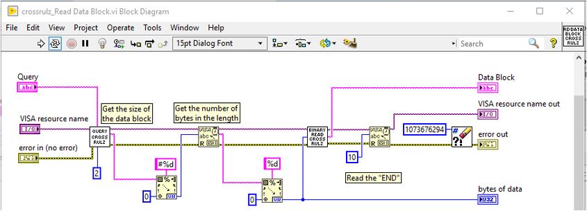
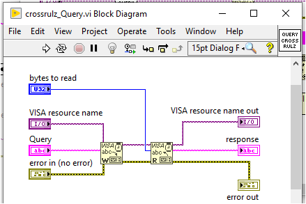
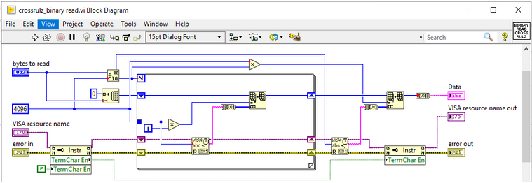
No. First write the command and then read 2 characters. Convert that response to know how many bytes to read next. Then read that number of bytes and convert to a number. Now read that number of bytes to read the actual block data. Here is the code I use to read these data blocks.

EDIT: I just noticed an error wire disappeared when I made the image. I assure you my errorr are properly propagated.
There are only two ways to tell somebody thanks: Kudos and Marked Solutions
Unofficial Forum Rules and Guidelines
"Not that we are sufficient in ourselves to claim anything as coming from us, but our sufficiency is from God" - 2 Corinthians 3:5
04-26-2023 07:56 PM
- Mark as New
- Bookmark
- Subscribe
- Mute
- Subscribe to RSS Feed
- Permalink
- Report to a Moderator
I implemented your version, but I get the same results.
I tried a different oscilloscope but got the same results.
There are three devices on the GPIB bus (two scopes and a DMM). All are powered.
John
"Praise the Lord and pass the ammunition."- Lt. (j.g.) Howell Forgy, Sky Pilot, USS New Orleans, 12/7/41
05-15-2023 11:46 AM
- Mark as New
- Bookmark
- Subscribe
- Mute
- Subscribe to RSS Feed
- Permalink
- Report to a Moderator
UPDATE: as it turns out, the Prologix controller has a history of not playing well with the Tek TDS scopes. Thanks to all who replied. It was both appreciated and educational.
"Praise the Lord and pass the ammunition."- Lt. (j.g.) Howell Forgy, Sky Pilot, USS New Orleans, 12/7/41


