- Subscribe to RSS Feed
- Mark Topic as New
- Mark Topic as Read
- Float this Topic for Current User
- Bookmark
- Subscribe
- Mute
- Printer Friendly Page
Counter and Analog Output mismatch
04-21-2016 01:15 PM
- Mark as New
- Bookmark
- Subscribe
- Mute
- Subscribe to RSS Feed
- Permalink
- Report to a Moderator
Hi All,
I have been trying to get my Analog Voltage out with the counter falling edge..
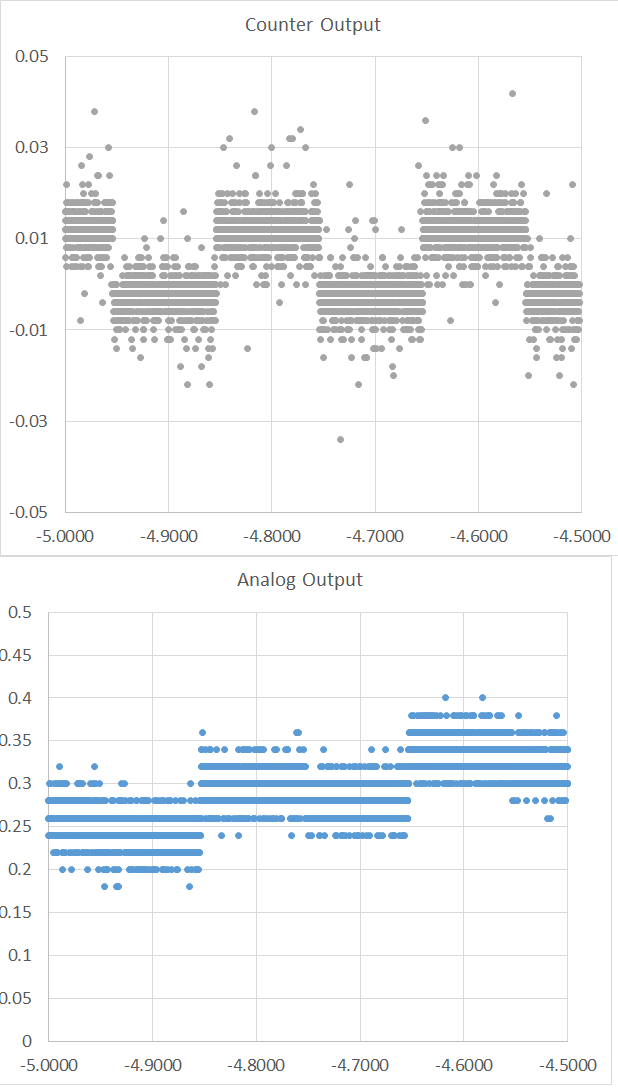
but here's the out put of the oscilloscope over 5 seconds..
Here's the code..
# DAQmx Configure Code for Digital Channel
    DAQmxCreateTask("",byref(taskHandleD))
    DAQmxCreateCOPulseChanTime(taskHandleD,"DAQ/ctr0","",DAQmx_Val_Seconds,DAQmx_Val_Low,0.00,LOW_TIME,HIGH_TIME)
    DAQmxCfgImplicitTiming(taskHandleD,DAQmx_Val_FiniteSamps,SAMPLE_SIZE)

    # DAQmx Configure Code
    DAQmxCreateTask("",byref(taskHandleAO))
    DAQmxCreateAOVoltageChan(taskHandleAO,"DAQ/ao1","",-10.0,10.0,DAQmx_Val_Volts,None)
    DAQmxCfgSampClkTiming(taskHandleAO,"PFI12",1000,DAQmx_Val_Falling,DAQmx_Val_FiniteSamps,SAMPLE_SIZE)
#    DAQmxCfgDigEdgeStartTrig(taskHandleAO,"PFI12", DAQmx_Val_Falling)
So here are my questions:
1. Why is the AO changing with the counter rising edge
2. I have a NI PCIe-6321, X Series DAQ (16 AI, 24 DIO, 2 AO) card. What is the value of the counter output voltage.. should it be a TTL signal?
3. As an aside, If I wanted to write the values of the analog input into a file (TDMS) what is the command I should use? I.e how do I do native Daqmx data logging as opposed to writing to a file using the coding language?
Thanks and regards,
Ravi
04-21-2016 03:03 PM
- Mark as New
- Bookmark
- Subscribe
- Mute
- Subscribe to RSS Feed
- Permalink
- Report to a Moderator
Attempting to help with limited time...
1. I have no idea how those graphs are supposed to illustrate that the AO changes on the counter pulse rising edge. There isn't nearly enough timing resolution, plus I have no idea what your analog output should be doing.
2. I program LabVIEW, but your syntax looks more or less correct for falling edge sensitivity, assuming the counter outputs to PFI12. However I would trigger on the rising (leading) edge to be sure the task "sees" the first falling edge as a sample clock.
3. The counter output should be TTL compatible and you can generally expect it to be pretty near 5V for logic high. Your graph doesn't seem to have caught any high states. Have no way of knowing if your counter failed to pulse, you weren't connected to the right pin, or the pulse is much shorter than the sample rate shown in the graph.
-Kevin P
04-22-2016
10:45 AM
- last edited on
04-28-2024
03:47 PM
by
![]() Content Cleaner
Content Cleaner
- Mark as New
- Bookmark
- Subscribe
- Mute
- Subscribe to RSS Feed
- Permalink
- Report to a Moderator
2) yes, it should be TTL (0-5 V) into high impedance load. You show +/- 5 mV, very close to the measurement noise level, something strange.
With digital lines you have 2 modes, Digital Output -> Type: sinking, sourcing:
Sinking basically inverts output relative to the counter value. (True = connect to ground, 0 Value). I do not know if there is similar setting for counters. Sourcing should be the default one.
Try to disconnect your equipment, start MAX, reset the board (set all to default), run continuous counter output task in test panels and check voltage output with a scope (1 MOhm impedance).
04-23-2016 07:16 PM
- Mark as New
- Bookmark
- Subscribe
- Mute
- Subscribe to RSS Feed
- Permalink
- Report to a Moderator
Hi Kevin / Alex,
not sure what the issue was, perhaps it was with the oscilloscope, or the cables, I switched output to another physical channel, and it read the 5V TTL as advertised, switched back to the previous channel and it now reads 5V too.
thanks for your inputs.. especially about the triggering, sinking/sourcing etc.
warmest regards,
Ravi


