-
NI Community
- Welcome & Announcements
-
Discussion Forums
- Most Active Software Boards
- Most Active Hardware Boards
-
Additional NI Product Boards
- Academic Hardware Products (myDAQ, myRIO)
- Automotive and Embedded Networks
- DAQExpress
- DASYLab
- Digital Multimeters (DMMs) and Precision DC Sources
- Driver Development Kit (DDK)
- Dynamic Signal Acquisition
- FOUNDATION Fieldbus
- High-Speed Digitizers
- Industrial Communications
- IF-RIO
- LabVIEW Communications System Design Suite
- LabVIEW Electrical Power Toolkit
- LabVIEW Embedded
- LabVIEW for LEGO MINDSTORMS and LabVIEW for Education
- LabVIEW MathScript RT Module
- LabVIEW Web UI Builder and Data Dashboard
- MATRIXx
- Hobbyist Toolkit
- Measure
- NI Package Manager (NIPM)
- Phase Matrix Products
- RF Measurement Devices
- SignalExpress
- Signal Generators
- Switch Hardware and Software
- USRP Software Radio
- NI ELVIS
- VeriStand
- NI VideoMASTER and NI AudioMASTER
- VirtualBench
- Volume License Manager and Automated Software Installation
- VXI and VME
- Wireless Sensor Networks
- PAtools
- Special Interest Boards
- Community Documents
- Example Programs
-
User Groups
-
Local User Groups (LUGs)
- Aberdeen LabVIEW User Group (Maryland)
- Advanced LabVIEW User Group Denmark
- ASEAN LabVIEW User Group
- Automated T&M User Group Denmark
- Bangalore LUG (BlrLUG)
- Bay Area LabVIEW User Group
- British Columbia LabVIEW User Group Community
- Budapest LabVIEW User Group (BudLUG)
- Chicago LabVIEW User Group
- Chennai LUG (CHNLUG)
- CSLUG - Central South LabVIEW User Group (UK)
- Delhi NCR (NCRLUG)
- Denver - ALARM
- DutLUG - Dutch LabVIEW Usergroup
- Egypt NI Chapter
- Gainesville LabVIEW User Group
- GLA Summit - For all LabVIEW and TestStand Enthusiasts!
- GUNS
- High Desert LabVIEW User Group
- Highland Rim LabVIEW User Group
- Huntsville Alabama LabVIEW User Group
- Hyderabad LUG (HydLUG)
- Indian LabVIEW Users Group (IndLUG)
- Ireland LabVIEW User Group Community
- LabVIEW LATAM
- LabVIEW Team Indonesia
- LabVIEW - University of Applied Sciences Esslingen
- LabVIEW User Group Berlin
- LabVIEW User Group Euregio
- LabVIEW User Group Munich
- LabVIEW Vietnam
- Louisville KY LabView User Group
- London LabVIEW User Group
- LUGG - LabVIEW User Group at Goddard
- LUGNuts: LabVIEW User Group for Connecticut
- LUGE - Rhône-Alpes et plus loin
- LUG of Kolkata & East India (EastLUG)
- LVUG Hamburg
- Madison LabVIEW User Group Community
- Mass Compilers
- Melbourne LabVIEW User Group
- Midlands LabVIEW User Group
- Milwaukee LabVIEW Community
- Minneapolis LabVIEW User Group
- Montreal/Quebec LabVIEW User Group Community - QLUG
- NASA LabVIEW User Group Community
- Nebraska LabVIEW User Community
- New Zealand LabVIEW Users Group
- NI UK and Ireland LabVIEW User Group
- NOBLUG - North Of Britain LabVIEW User Group
- NOCLUG
- NORDLUG Nordic LabVIEW User Group
- North Oakland County LabVIEW User Group
- Norwegian LabVIEW User Group
- NWUKLUG
- Orange County LabVIEW Community
- Orlando LabVIEW User Group
- Oregon LabVIEW User Group
- Ottawa and Montréal LabVIEW User Community
- Phoenix LabVIEW User Group (PLUG)
- Politechnika Warszawska
- PolŚl
- Rhein-Main Local User Group (RMLUG)
- Romandie LabVIEW User Group
- Rutherford Appleton Laboratory
- Sacramento Area LabVIEW User Group
- San Diego LabVIEW Users
- Sheffield LabVIEW User Group
- Silesian LabVIEW User Group (PL)
- South East Michigan LabVIEW User Group
- Southern Ontario LabVIEW User Group Community
- South Sweden LabVIEW User Group
- SoWLUG (UK)
- Space Coast Area LabVIEW User Group
- Stockholm LabVIEW User Group (STHLUG)
- Swiss LabVIEW User Group
- Swiss LabVIEW Embedded User Group
- Sydney User Group
- Top of Utah LabVIEW User Group
- UKTAG – UK Test Automation Group
- Utahns Using TestStand (UUT)
- UVLabVIEW
- VeriStand: Romania Team
- WaFL - Salt Lake City Utah USA
- Washington Community Group
- Western NY LabVIEW User Group
- Western PA LabVIEW Users
- West Sweden LabVIEW User Group
- WPAFB NI User Group
- WUELUG - Würzburg LabVIEW User Group (DE)
- Yorkshire LabVIEW User Group
- Zero Mile LUG of Nagpur (ZMLUG)
- 日本LabVIEWユーザーグループ
- [IDLE] LabVIEW User Group Stuttgart
- [IDLE] ALVIN
- [IDLE] Barcelona LabVIEW Academic User Group
- [IDLE] The Boston LabVIEW User Group Community
- [IDLE] Brazil User Group
- [IDLE] Calgary LabVIEW User Group Community
- [IDLE] CLUG : Cambridge LabVIEW User Group (UK)
- [IDLE] CLUG - Charlotte LabVIEW User Group
- [IDLE] Central Texas LabVIEW User Community
- [IDLE] Cowtown G Slingers - Fort Worth LabVIEW User Group
- [IDLE] Dallas User Group Community
- [IDLE] Grupo de Usuarios LabVIEW - Chile
- [IDLE] Indianapolis User Group
- [IDLE] Israel LabVIEW User Group
- [IDLE] LA LabVIEW User Group
- [IDLE] LabVIEW User Group Kaernten
- [IDLE] LabVIEW User Group Steiermark
- [IDLE] தமிழினி
- Academic & University Groups
-
Special Interest Groups
- Actor Framework
- Biomedical User Group
- Certified LabVIEW Architects (CLAs)
- DIY LabVIEW Crew
- LabVIEW APIs
- LabVIEW Champions
- LabVIEW Development Best Practices
- LabVIEW Web Development
- NI Labs
- NI Linux Real-Time
- NI Tools Network Developer Center
- UI Interest Group
- VI Analyzer Enthusiasts
- [Archive] Multisim Custom Simulation Analyses and Instruments
- [Archive] NI Circuit Design Community
- [Archive] NI VeriStand Add-Ons
- [Archive] Reference Design Portal
- [Archive] Volume License Agreement Community
- 3D Vision
- Continuous Integration
- G#
- GDS(Goop Development Suite)
- GPU Computing
- Hardware Developers Community - NI sbRIO & SOM
- JKI State Machine Objects
- LabVIEW Architects Forum
- LabVIEW Channel Wires
- LabVIEW Cloud Toolkits
- Linux Users
- Unit Testing Group
- Distributed Control & Automation Framework (DCAF)
- User Group Resource Center
- User Group Advisory Council
- LabVIEW FPGA Developer Center
- AR Drone Toolkit for LabVIEW - LVH
- Driver Development Kit (DDK) Programmers
- Hidden Gems in vi.lib
- myRIO Balancing Robot
- ROS for LabVIEW(TM) Software
- LabVIEW Project Providers
- Power Electronics Development Center
- LabVIEW Digest Programming Challenges
- Python and NI
- LabVIEW Automotive Ethernet
- NI Web Technology Lead User Group
- QControl Enthusiasts
- Lab Software
- User Group Leaders Network
- CMC Driver Framework
- JDP Science Tools
- LabVIEW in Finance
- Nonlinear Fitting
- Git User Group
- Test System Security
- Developers Using TestStand
- Product Groups
-
Partner Groups
- DQMH Consortium Toolkits
- DATA AHEAD toolkit support
- GCentral
- SAPHIR - Toolkits
- Advanced Plotting Toolkit
- Sound and Vibration
- Next Steps - LabVIEW RIO Evaluation Kit
- Neosoft Technologies
- Coherent Solutions Optical Modules
- BLT for LabVIEW (Build, License, Track)
- Test Systems Strategies Inc (TSSI)
- NSWC Crane LabVIEW User Group
- NAVSEA Test & Measurement User Group
-
Local User Groups (LUGs)
-
Idea Exchange
- Data Acquisition Idea Exchange
- DIAdem Idea Exchange
- LabVIEW Idea Exchange
- LabVIEW FPGA Idea Exchange
- LabVIEW Real-Time Idea Exchange
- LabWindows/CVI Idea Exchange
- Multisim and Ultiboard Idea Exchange
- NI Measurement Studio Idea Exchange
- NI Package Management Idea Exchange
- NI TestStand Idea Exchange
- PXI and Instrumentation Idea Exchange
- Vision Idea Exchange
- Additional NI Software Idea Exchange
- Blogs
- Events & Competitions
- Optimal+
- Regional Communities
- NI Partner Hub
-
 Petru_Tarabuta
on:
Some Boring Statements
Petru_Tarabuta
on:
Some Boring Statements
-
 ManuelSebald
on:
LabVIEW and Linux Review
ManuelSebald
on:
LabVIEW and Linux Review
-
 swatts
 on:
LabVIEW in a Box!
on:
LabVIEW in a Box!
-
 Taggart
on:
Influence
Taggart
on:
Influence
-
swatts
on:
TMiLV (This Month in LabVIEW) - Definitely NOT another podcast!
-
swatts
on:
AI is going to take our jobs - everyone should panic now.
-
swatts
on:
LabVIEW Firmata - Easy control of Arduino Microcontrollers
-
 Dhakkan
on:
LabVIEW OpenSUSE Leap15.5 on a LattePanda V1
Dhakkan
on:
LabVIEW OpenSUSE Leap15.5 on a LattePanda V1
-
swatts
on:
LabVIEW and Linux - Intro
-
swatts
on:
It's time for me time.
As requested:-A typical SSDC Project
- Subscribe to RSS Feed
- Mark as New
- Mark as Read
- Bookmark
- Subscribe
- Printer Friendly Page
- Report to a Moderator
In the blog before last it was suggested that it would be beneficial to run through a typical job. Bit of a dry subject if you ask me!!!, to liven it up I've done some more cartoons 
Here's a few statistics about us, not for ego reasons (although we're awesome), but just to give a feel for the kind of business we run. We have about 50 customers on our books. They are mostly in Aerospace, Automotive, Military, Manufacturing, Academia and Transport. We like repeat business and most of our work is fixed-price, we do both hardware and software. Splitting our work into small, medium and large flavours (2-4 man weeks, 5-16 man weeks, 17+ man weeks) it's about 20:40:40 at a guess. 90% of our jobs have no specification at the start, generally it's a discussion, referenced to existing systems. The level of paper-work we do rather depends on our understanding of the job or our relationship with the customer. We usually provide a target specification and quote (essentially telling the customer what we will deliver and how much it will cost), fairly often we do an initial milestone where we do feasibility, design reviews and provide a final cost. 95% of our projects don't need anything dynamic or concurrent. Is that because we only get simple work or that we choose to work simply? |  |
We tackle the risky parts of the project as early as possible.
So I thought rather than live in a world of Unicorns and Rainbows I would run through a project that went averagely, rather than badly or perfectly. Most importantly we made money and it transpires that the customer thought it might never work (which was nice of them!).
Brief Description of System
It's a filter test system consisting of 2 controllable fans, 2 servo valves, loads of transducers for logging, control and calibration, some relays. It will be used for experiments as well as stepped testing. The control algorithm is a contrived calculation of 1 or more of the transducers.
A couple of meetings and an exchange of paper-work and we we're up and running (although a little cost constrained). We would provide the instrumentation, the software, the tools to set up the system and documentation.
Our general approach is as follows (with variants depending on the risks)
|  |
We have a general application template in our armoury that is useful for 80%+ of our projects and this consists of the following functionality.
Wizard based front panel, consisting of initialise, event structure, state machine and Queued Message Screen update.
This has several built in components as described below, you can guess how they are built from my previous blogs.
Config
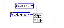
This component handles all configurable items, via an enumerated type called parameter. To add a new parameter just add an item to the enumerated type
No Command – Error | This the default condition and will get quite indignant if called. |
Initialise Config to SQLite | This command sets the configuration instance to use the SQLite database. Other databases and file type ini methods are available. |
Save Config | Saves and up-issues the configuration database |
Get Key | Gets a key as selected by parameter |
Set Key | Sets a key as selected by parameter |
Update Key | Updates a key in the database without up-issuing |
Get Latest Config Data | Caches configuration data |
Get Config Data for Version | Gets configuration data for a specific version |
The supporting cast for this component consists of database components as described in previous blogs, and an intermediate component that does the SQL.
Error
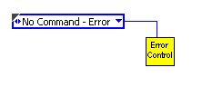
This component handles error reporting in a fairly rudimentary manner.
No Command – Error | This the default condition and will get quite indignant if called. |
Set to Dev Mode | In development mode it loudly complains. |
|---|---|
Set to Released Mode | When released it stores errors to a log file. |
Set Error | Either throws up the dialog, or files the error depending on mode. |
Log Error | Forces a file store. |
Throw Error | Throws up the error dialog |
Log and Throw Error | Does both |
Set Error Timed | Throws up the error dialog, for a preset time. |
UI Control
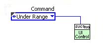
This component passes commands to the UI update loop, there are several versions of this component, but they all perform similar functionality.
| Under Range | This the default condition and will get quite indignant if called. |
Exit | Close the queue and exit |
Get FP Setting | If anything is on the Q, pass it out. |
Get Q Ref | Pass out the Q Ref, just the once to allow it to hold the UI Loop. |
Set Status | This is a command to send text to the status text box on the main screen. |
Set Tab | This selects the tab to be displayed on the main screen (how we get our wizard going) |
etc etc | Screen update command as required, all screen updates should ideally go through this component. |
As mentioned earlier tend to push risks to the front of our projects and for this one the identifiable risk was that the control system wouldn't work. We didn't want to be held liable for a system we had little expertise in, with this in mind we required that the customer pay for the hardware, prototype screen and engineering screen. The prototype screen is essentially a button functional screen that allows the customer to navigate around the system. By using this template we can get a prototype screen together in a matter of hours (we usually allow a day for this size of project). The cost constraints of the project made us go for 4 process controllers using RS485 to talk to them. We insisted on Ethernet cDAQ for the measurement system at least! The biggest risk here was talking to the process controllers and therefore that should be tackled first. It was a standard modbus communications and we had a component for that to reuse. This component was then called by the process controller component. |  |
Process Controller Component

Communicates to any process controller on a single port.
No Command – Error | This the default condition and will get quite indignant if called. |
Initialise Set Setpoint 1 Get Setpoint 1 Get Process Variable Set Proportional Get Proportional Get Setpoint 2 Set Setpoint 2 Reset Get version Get Bus Format Set for RS232 Set for RS485 Get Derivative Set Derivative Get Integral Set Integral Get Output Config Set Output Config Get Input Config Set Input Config Get Alarm Status Get Reading Format Set Reading Format Get Input Scale Set Input Scale Get Cycle Time Set Cycle Time Close All | At this stage in the project I was expecting to use auto-tune to get the PID parameters and also to set the controller up completely different for each test/filter. Hence the over-load of functions for this component. |
For convenience this component was then wrapped in a batch controller component that did stuff to all 4 controllers. Components to talk to the measurement system were also written. These were essentially DAQmx tasks wrapped up in components that describe the system. i.e. Control An Ins, Measure An Ins etc etc. With these written and tested, a manual screen (engineering screen) was produced that gave access to the available hardware functionality and the system was delivered to the customer. This allowed us to get paid for the first milestone and to test some control set-ups. The initial plan (I was sceptical) was to do closed loop control the fans and the servo valve, it transpired that servo valve could not be controlled in a timely fashion by the process controller for all the variations of test. Also the Fans and Servo valves squabbled causing instability. The process controller set up software was extremely poor and they were a bit more stupid than expected. After too much time playing with the system we came up with a method that worked and controlled very nicely. We then added components to handle calibration data, Valve setting lookup, set-up wizard display, Apply Closed Loop Calculation, Orifice Plate dB. A component was also added to Queue up Hardware commands to free up the control algorithm from slow communication operations. |  |
The Beta system was then delivered and an intensive session of testing was undertaken.
 | What went well....The system was delivered, working, when the customer needed it, we got paid, customer pleased. |
What went badly...The process controllers cost a great deal more time to get working and set-up satisfactorily than expected. The agreement that the customer do all the testing and setting up of the system didn't transpire how we expected. In the end we pretty much did it all. This cost us about a week. On the upside we are now the system experts. From a design perspective I think I over-used value signalling (a quick bodge to convert the manual screen to an auto-test screen). It all worked wonderfully but I found it made the software harder to read. |  |
That felt a bit like homework, so don't expect me to write many articles like this!!
Hope it's of use to those that requested it.
Lots of Love
Steve
PS the cartoon is reasons not to take on a job, I'm sure there are more (7 Deadly ones for example!)
Steve
Opportunity to learn from experienced developers / entrepeneurs (Fab,Joerg and Brian amongst them):
DSH Pragmatic Software Development Workshop
- Tags:
- design
You must be a registered user to add a comment. If you've already registered, sign in. Otherwise, register and sign in.
